
A gyroscope sensor becomes valuable in industry only when its angular-rate data survives the real environment. A laboratory data sheet may show excellent bias or noise, yet the deployed system must also tolerate vibration, temperature gradients, misalignment, electrical interference, and gaps in external navigation. The engineering question is therefore not simply whether gyroscope sensors can detect rotation. It is whether their output remains trustworthy enough to stabilize a platform, guide a vehicle, control a robot, or preserve orientation when other references become unreliable.
Why Gyroscope Sensors Move from Lab Accuracy to Industrial Value
How gyroscope sensors measure angular rate in a working machine
Mechanical and dynamically tuned gyroscopes use a spinning or vibrating element whose response changes under rotation. MEMS devices commonly detect Coriolis motion in a vibrating microstructure, while fiber-optic gyroscopes measure the phase difference between counter-propagating light paths. Each approach ultimately produces angular rate, usually in degrees per second or radians per second. Integrating that rate estimates angle, but any offset is integrated too; even a small bias therefore becomes growing attitude error. The underlying technologies and their industrial roles are summarized in the peer-reviewed review by Passaro et al.
Where bias, noise, range, and bandwidth become operational limits
Four parameters deserve early attention. Bias stability limits how quickly an unaided heading drifts. Angle random walk describes noise-driven uncertainty over time. Measurement range must cover the fastest credible rotation without saturation, while bandwidth must pass the motion a controller needs to see. A wider range or bandwidth is not automatically better: either can reduce effective resolution or admit unnecessary noise. Cross-axis sensitivity, scale-factor error, warm-up behavior, and temperature coefficients belong in the same error budget because they decide whether a nominally accurate sensor remains accurate after installation.
Industrial Gyroscope Sensors Across Real-World Applications
Robotics, stabilization, and motion control
Industrial robots, gimbals, mobile machines, and antenna platforms use gyroscope sensors to detect fast rotational disturbances before slower external references can respond. The angular-rate loop suppresses oscillation and stabilizes pointing; an accelerometer, encoder, camera, or other reference then corrects long-term drift. In human-machine interfaces, wearable gyroscopic and accelerometric data can also map gestures to robotic-arm commands, although safety-rated motion still requires independent limits and validation.
Navigation continuity for vehicles, marine systems, and autonomous platforms
Inertial navigation depends on gyroscopes for attitude propagation between GNSS, odometer, Doppler velocity log, camera, or magnetic updates. During a tunnel passage, multipath event, or underwater interval, the gyro keeps the navigation solution continuous, but accuracy decays according to the sensor error model and outage duration. This is why selection should start with the maximum unaided interval and allowable attitude error, not with a generic grade label. Industrial MEMS systems are often attractive where size, power, update rate, and cost matter; higher-stability technologies become justified as outage or pointing requirements tighten.
Drilling, surveying, and high-temperature orientation
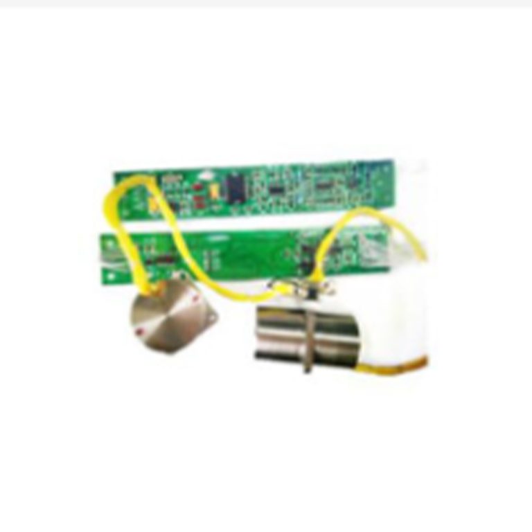
Downhole drilling combines shock, vibration, restricted space, and elevated temperature. Orientation must remain usable where satellite and magnetic references may be weak or unavailable. Our ADL-DTG-E2 is designed for drilling fields and is specified for operation up to 100 degrees Celsius, reflecting the temperature-adaptation and service-life demands of that environment. The relevant buying decision is not just the temperature limit: qualification should also cover thermal cycling, warm-up time, vibration exposure, connector integrity, and recalibration intervals under the actual tool profile.
Choosing Gyroscope Sensor Technology for the Mission
MEMS, dynamically tuned, and fiber-optic gyroscope trade-offs
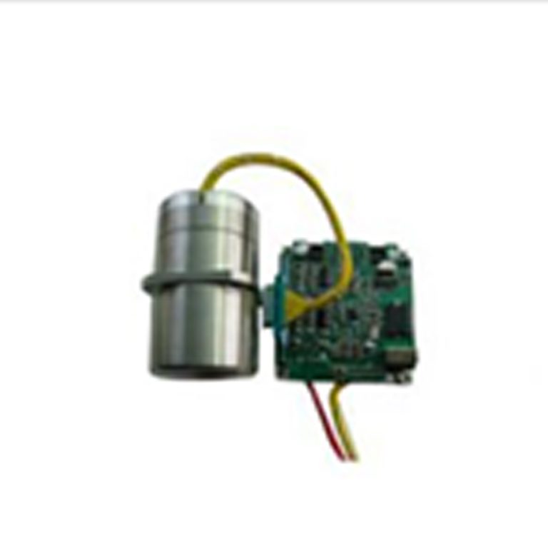
MEMS gyroscopes favor compact packaging, low power, shock tolerance, and straightforward digital integration. Dynamically tuned gyroscopes can provide higher stability for demanding orientation and navigation tasks, while fiber-optic designs remove moving mechanical parts and suit applications requiring strong stability and reliability. No technology wins every mission. The choice depends on drift tolerance, dynamics, environment, power, volume, interface, startup time, serviceability, and total system cost. Andelu offers MEMS/IMU, dynamically tuned, and fiber-optic options so we can match the sensing principle to the deployment rather than force one architecture across all platforms.
When an IMU is more useful than a standalone gyroscope
A standalone gyro is appropriate for a rate loop or an existing multi-sensor design. An inertial measurement unit is usually better when the controller needs synchronized three-axis angular rate and acceleration, common timing, calibrated axes, and a defined interface. Sensor fusion can use gravity, vehicle motion, or external observations to bound gyro drift. However, fusion cannot rescue poor timestamps, unknown axis mapping, mechanical flex, or saturation. Procurement teams should therefore ask whether calibration, synchronization, temperature compensation, and interface behavior are delivered at component, IMU, or navigation-system level.
Engineering Gyroscope Sensors into a Reliable System
Mounting, alignment, thermal compensation, and calibration
The sensitive axes must be aligned to the machine coordinate frame and mounted on a surface stiff enough to avoid local resonance. Installation stress can shift bias; remote mounting can introduce flex; temperature gradients can invalidate a single-point compensation model. A practical calibration plan checks zero-rate output, scale factor, axis orthogonality, temperature response, and repeatability after shock or service. When the gyro sits away from the platform reference point, engineers should also model rotational lever-arm effects in the fused solution.
Sampling, filtering, interfaces, and sensor fusion
Sampling must exceed the useful motion bandwidth with enough margin for anti-alias filtering. Control loops need predictable latency and timestamp quality, not merely a high nominal output rate. RS422, CAN, SPI, or other interfaces should be evaluated for cable length, grounding, error detection, and integration effort. Filters must preserve the phase response required by stabilization while rejecting structural vibration outside the control band. Record firmware, filter settings, calibration coefficients, sensor orientation, and timing configuration with field data; otherwise a configuration change may look like physical degradation.
Deployment Risks That Specifications Alone Do Not Reveal
Vibration rectification, shock, temperature cycling, and EMI
A gyro exposed to vibration can develop a false rate through nonlinear response, even when the vibration frequency lies outside the stated signal band. Shock may cause a temporary offset or permanent shift. Temperature cycling tests compensation repeatability, while electromagnetic interference can corrupt power, clocks, or communication. These effects are installation-specific. Qualification should reproduce the mounting, enclosure, cabling, power supply, and representative vibration spectrum rather than test the loose sensor in isolation.
Field validation and lifecycle data integrity
Before deployment, compare gyro output with a traceable turntable, encoder, or reference inertial system across rate, temperature, and orientation. Then run the complete machine through normal and worst-case duty cycles. Field monitoring should track zero-rate behavior, temperature, communication errors, saturation events, and residuals from sensor fusion. Acceptance limits must connect to the operational consequence: pointing error, lane deviation, borehole orientation uncertainty, or controller stability. This turns sensor health into an actionable maintenance signal rather than an unexplained diagnostic number.
A Practical Gyroscope Sensor Selection Workflow
Translate the mission into an error budget
Define the smallest useful rotation, maximum rate, required bandwidth, allowable angle drift, outage duration, startup time, temperature range, vibration and shock exposure, interface, power, size, and safety consequence. Allocate the attitude-error budget across bias, noise, scale factor, alignment, timing, and external aiding. Only then compare candidates. This prevents a low headline bias from hiding inadequate range, thermal behavior, or latency.
Verify performance before full industrial deployment
Use a staged gate: bench calibration, environmental testing, hardware-in-the-loop evaluation, limited field trials, and production acceptance testing. Preserve raw data during failures and review whether errors came from the sensing element, mounting, electronics, timing, or fusion logic. At Andelu, we recommend sharing the platform dynamics, environment, interface, and accuracy objective early so our gyroscope sensor portfolio can be evaluated against a real mission profile. A deployable solution is the sensor, mechanics, calibration, electronics, software, and validation plan working together.
SSS
What are gyroscope sensors used for in industry?
Gyroscope sensors measure angular rate for robotic motion control, platform stabilization, vehicle and marine navigation, drilling orientation, surveying, and machinery attitude monitoring. They are especially useful when fast rotational feedback or short-term navigation continuity is required.
How accurate are industrial gyroscope sensors?
Accuracy depends on bias stability, angle random walk, scale factor, temperature compensation, vibration response, and calibration. The required grade should be selected from the allowable angle drift and unaided operating time, not from one headline specification.
What is the difference between a gyroscope sensor and an IMU?
A gyroscope sensor measures angular rate. An IMU combines gyroscopes with accelerometers, usually across three axes, and may include calibration and synchronization. Choose an IMU when the system needs coordinated rotational and linear-motion data for sensor fusion.
Sources
[1] Passaro, V. M. N., et al. “Gyroscope Technology and Applications: A Review in the Industrial Perspective” [J]. Sensors, 2017.
[2] Gyroscope.com. “What Are the Applications of Gyroscopes?” [EB/OL]. Gyroscope.com.
[3] Blikai. “Gyroscope Sensor: Working, Types & Applications” [EB/OL]. Blikai.
[4] Semiconductor for You. “Gyroscope Sensor: Working and Its Applications” [EB/OL]. Semiconductor for You.
[5] Origin-IC. “Exploring the Versatility of Gyroscope Sensors in Modern Technology” [EB/OL]. Origin-IC, 2025.
[6] Analog Devices. “Accelerometer and Gyroscopes Sensors: Operation, Sensing, and Applications” [EB/OL]. Analog Devices.
[7] Unmanned Systems Technology. “The Evolution of Gyroscopes in Modern Navigation and Sensor Systems” [EB/OL]. Unmanned Systems Technology.
[8] Ocean Science & Technology. “Industrial and Tactical Applications of MEMS Inertial Sensors” [EB/OL]. Ocean Science & Technology.
[9] SBG Systems. “Industrial-Grade IMU” [EB/OL]. SBG Systems.
[10] Cazacu, C. C. “Controlling Industrial Robotic Arms Using Gyroscopic and Accelerometric Data” [J]. Applied Sciences, 2025, 15(15): 8297.
[11] Andelu. “Gyro Sensor Product Category” [EB/OL]. Andelu Technology.
[12] Andelu. “Oil and Gas DTG Gyroscope ADL-DTG-E2” [EB/OL]. Andelu Technology.