
INS navigation often gets viewed as a sensor-accuracy issue. In real-world field use, it comes down to system architecture. Inertial errors, aiding signals, time sync, mounting setup, and estimator rules all work together. A strong IMU can still give weak results if its frame sits misaligned or external data arrives late. On the other side, a basic sensor can deliver solid continuity once the system shows its uncertainty, adds helpful aiding, and spots bad inputs. This piece lays out a design approach for motion sensing that must stay reliable on vehicles, unmanned platforms, marine gear, and aircraft.
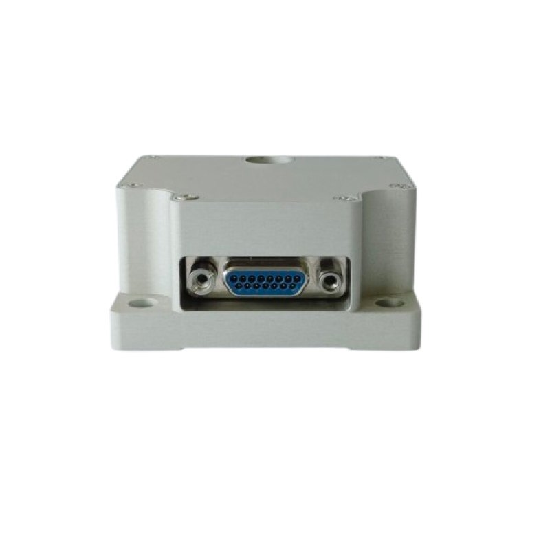
INS navigation starts with a mission-linked error budget
Specify the output requirements rather than referring to a spec sheet. Define a number of constraints including position and attitude, longest unaided operation, vehicle motion, vibration, temperature, start-up time and output rate. A road vehicle with fixed satellite coverage can tolerate more drift than a surveying application crossing a long tunnel or a marine application that requires constant heading at slow speeds. The mission profile defines which errors are most critical and which aiding can be used to correct them.
A fixed error that calibration can remove from random errors that increase with time and noise is split up here for the simple case of horizontal motion. A constant accelerometer bias leads to errors in velocity near b_a t and in position near ½ b_a t². A tilt error θ causes gravity to leak into the horizontal direction and leads to errors in the accelerometer signal close to gθ. Thus, even a small attitude offset can cause a position to increase, even if the noise of the accelerometer seems to be small. Earth rate, transport rate, coning, sculling, and even closed-loop aiding have to be considered for a full analysis.
Pick gyroscopes and accelerometers as one inertial core.
Turn sensor specs into navigation impact
The short-term attitude spread is determined by the gyro angle random walk, while the heading drift over longer times is determined by the bias instability and the turn-on repeatability. The errors of the accelerometer bias and the velocity random walk determine the velocity and position errors. The scale-factor error increases with the magnitude of the specific force and depends on its direction. Noise density has to be distinguished from bias stability. While the noise density describes a wideband random noise, the Allan deviation describes how an error behaves over time. The errors in the inertial parts can be detected by means of the Allan-variance plots, where white noise, bias instability, and rate random walk can be identified.
Acceleration and vibration must be within the dynamic range of the sensor to avoid clipping. The bandwidth of the sensor must be matched to the rate of motion of the object being estimated or controlled. Wider bandwidth means more vibration and the potential for aliasing. Other error sources that must be modeled include cross-axis sensitivity, non-orthogonality, g-sensitivity, thermal drift, and sensor mounting stresses. A single “resolution” number is not very informative without associated bandwidth, averaging time, temperature, and test conditions.
Match technology to stability, size, and build needs
MEMS inertial sensors are small, consume low power, and can easily be connected to the electronic system of a robot, a car, or an unmanned application. However, as with any sensor, there are some limitations such as bias drift, vibration sensitivity, and temperature influence. Inertial measurement units based on quartz flexure accelerometers make use of a well-established force-rebalance principle which allows for good repeatability and robustness against environmental influences. As a sensor for acceleration, a resonant quartz or silicon part changes its resonance frequency depending on acceleration. The digital output is clean. However, as with any sensor technology, there is no single technology that is the best for all applications. When comparing a fully calibrated system over the entire mission profile, including warm-up time, shock, vibration, and long-term repeatability, the choice of sensor technology becomes clear.
Build aiding around observability, not sensor count
An inertial mechanization can compute and update attitude, velocity, and position at high rates. An estimator can then compute the error states by comparing this solution with measurements from other sensors. A common error-state Kalman filter is then used to keep the main state solution updated with the measured rate and force, and to estimate the small errors in the attitude, velocity, position, etc. measurements as well as the sensor biases. The measurement updates then correct the main solution. This approach keeps the linearization errors under control and clearly shows the uncertainty in the solution.
Match GNSS coupling to the signal setting
Loose coupling of receiver position/velocity to INS is simple to implement/mount/test, but requires a full receiver position fix. Tight coupling of pseudorange/Doppler to INS navigation in a single filter uses all available satellite data, including partial views of the sky, to form a fix when a standalone fix is not possible with the number of signals available. Ultra-tight coupling of INS predictions to receiver tracking loops can aid weak signal or high dynamic situations, but adds significant complexity to the receiver and test work. Choose a level of coupling based on outage, data availability, and development time, not just because it is available.
Add platform rules with clear validity checks.
Odometer speed, non-holonomic motion rules, barometric height, Doppler velocity log, or dual-antenna heading are some of the sensors that increase observability when their conditions are met. A vehicle non-holonomic motion rule typically assumes zero side and vertical speed at the location of the sensor. Sideslip, rough terrain, or wheel lift can destroy this model. Odometer aiding fails due to wheel slip or tire-radius changes. Dual-antenna heading is used at low speed, yet it requires a rigid mounting and known geometry. Gate or down-weight data can be used when residuals, health flags, or physical checks indicate a problem. From vehicle studies, it is known that motion rules can limit drift but only as long as the motion is valid.
Treat timing, calibration, and installation as core parts
Control frames, latency and lever arms
Establish body, IMU, antenna and vehicle frames and define their axes and handedness. Measure the rotation between a coordinate system’s axes and the vehicle’s datum frames and check signs while making a controlled turn. A timestamp offset Δt during rotation results in an apparent attitude mismatch which increases with angular rate x Δt. Position and velocity measurements must be associated with the correct timestamp. Receiver delay and transport delay must be modeled and removed from the measurements.
The distance r between the center of mass of the GNSS antenna phase center and the origin of the IMU in body coordinates, plus the effects of rotation around this point of r, of velocity ω × r and of acceleration ω²r + 2v·ω, measured at the antenna relative to the IMU, add up to a constant offset, which the filter then mistakenly interprets as sensor bias. Survey the lever arm in the chosen body frame, and make sure the mount is as rigid as possible. Note whether the results are expressed in IMU coordinates, in antenna coordinates, or somewhere in between.
Calibrate the full unit across its operating range
Lab calibration is used to determine bias, scale factor, axis misalignment, etc. of sensors. System-level calibration is used to determine influences of the install and interfaces of the sensor to the system. Static multi-position tests are used to determine accelerometer bias and scale-factor terms. Rate-table tests are used to determine gyro scale factor, cross-axis response, and dynamic alignment. Thermal sweeps require realistic ramps and hold times to determine thermal lag effects. Acceptance records must be taken for a duration, bandwidth, temperature, test for vibration testing, etc., and the uncertainty of the test. Similar specs. cannot be compared if they are not recorded.
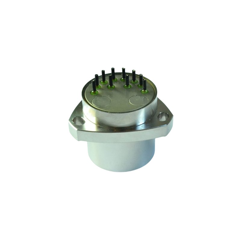
Build resilience into data and fault handling
Monitor for sensor saturation, high temperature, broken links, old measurements, and new filter innovations. Residuals will indicate poor aiding but must be physically diagnosed. Redundant sensors improve fault detection only if failure modes are not shared for axes, power, clocks, and mount. Independent inertial, satellite, and vehicle-motion paths should have quality flags propagated through the output interface. Downstream control can then discriminate between a good fix and a growing proposed solution.
The mechanical and electromagnetic setting of the sensor is part of the design. The IMU has to be mounted on a stiff reference. Local resonances have to be avoided. Thermal gradients have to be limited. Cable strain has to be eased. For the GNSS receiver, a clear sky view has to be ensured, and reflection and RF noise have to be reduced. Isolation has to be set from the measured platform spectra. A soft mount can cut high-frequency vibration but adds low-frequency motion and phase lag. Therefore, the full assembly has to be tested on vibration and thermal simulations instead of qualifying the sensor-core alone.
Apply the architecture to Andelu sensing systems
Our product range consists of MEMS IMUs, inertial navigation systems as well as GNSS/INS hybrid units, single-axis gyros and single-axis accelerometers. We can always pair a suitable sensing core with an appropriate aiding setup. The ADL-EX8-4N sensors are MEMS IMUs, which are equipped with a magnetometer, a barometer, and a multi-constellation receiver. The unit has temperature-compensated sensors and system-level self-calibration. The output can be configured as required. The ADL-MINS-5610 inertial sensors support single-antenna dynamic alignment as well as dual-antenna orientation aid. In addition, they are able to process multi-mode and multi-frequency GNSS signals and support RTK. Furthermore, there are interfaces for an odometer, a DVL, as well as for barometric height measurement. The performance depends on correct installation, setup, and operation.
For product-family details, see our MEMS IMU and INS solutions, integrated navigation solutions, as well as our range of accelerometers. Select from a number of different parameters including outage length and drift, and view the configured unit against your specific mission profile.
Use a practical selection and verification sequence
First, turn the mission into measurable limits: unaided time, position and attitude error, dynamics, environment, startup and update rate. Second, assign an error budget to gyro noise and bias, accelerometer bias and scale factor, initial alignment, aiding, timing, and lever arms. Third, shortlist sensor grades with comparable test conditions and Allan-variance data rather than one quoted figure. Fourth, define the aiding setup and each measurement’s validity rules. Finally, test alignment, thermal changes, vibration, typical maneuvers, satellite loss, recovery, and interface faults. Review error-state estimates and residuals as well as position output. This sequence shows whether the limit comes from sensor quality, observability, installation, or software before redesign costs rise.
The strongest INS navigation design does not necessarily include the most number of sensors, or the most complex filter. Rather, it is a design whose error growth is budgeted and whose aiding assumptions remain observable and testable. Most importantly, the design holds up to calibration after installation. By treating sensing, estimation, timing, and mechanics as one architecture, one can develop a defensible performance claim, and design a system to be diagnosed as conditions move away from ideal.
References
[1] P. G. Savage, “Strapdown Inertial Navigation Integration Algorithm Design, Part 1: Attitude Algorithms,” Journal of Guidance, Control, and Dynamics, vol. 21, no. 1, 1998, pp. 19–28. doi:10.2514/2.4228.
[2] N. El-Sheimy, H. Hou and X. Niu, “Analysis and Modeling of Inertial Sensors Using Allan Variance,” IEEE Transactions on Instrumentation and Measurement, vol. 57, no. 1, 2008, pp. 140–149. doi:10.1109/TIM.2007.908635.
[3] P. D. Groves, Principles of GNSS, Inertial, and Multisensor Integrated Navigation Systems, 2nd ed., Artech House, 2013.
[4] E.-H. Shin, Estimation Techniques for Low-Cost Inertial Navigation, Ph.D. dissertation, University of Calgary, 2005.
[5] F. Gustafsson and F. Gunnarsson, “Mobile Positioning Using Wireless Networks: Possibilities and Fundamental Limitations Based on Available Wireless Network Measurements,” IEEE Signal Processing Magazine, vol. 22, no. 4, 2005, pp. 41–53. doi:10.1109/MSP.2005.1458284.
[6] P. G. Savage: “Strapdown Inertial Navigation Integration Algorithm Design, Part 2: Velocity and Position Algorithms”, Journal of Guidance, Control, and Dynamics, Vol. 21, No. 2, 1998, pp. 208–221. doi: 10.2514/2.4242.