
In a multi-sensor navigation system, a gyroscope cannot be evaluated as an isolated component. Its bias, noise, scale factor, bandwidth, timing behavior, and environmental sensitivity influence the complete state-estimation chain. These errors affect not only angular-rate measurement but also attitude propagation, gravity compensation, velocity integration, position estimation, and the consistency of external sensor updates.
The relevant engineering question is therefore not limited to the nominal accuracy of the gyroscope. Rather, it concerns how the gyroscope behaves within the intended multi-sensor fusion architecture and whether its error characteristics can be effectively modeled, observed, estimated, and isolated under representative operating conditions.
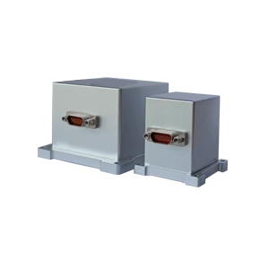
The Gyroscope as a State Propagation Sensor
A strapdown inertial navigation system calculates attitude by integrating angular-rate measurements. A practical gyroscope measurement model can be expressed as



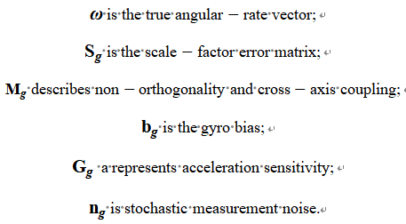
The attitude solution evolves continuously from this measurement. For a short interval, the attitude error caused by a nearly constant residual bias may be approximated as
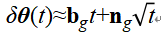
The bias contribution grows approximately linearly, whereas the noise contribution behaves as a random process. This attitude error then affects the transformation of measured specific force from the body frame
For small attitude errors, the resulting acceleration error contains a gravity-coupled term:

Even a small roll or pitch error can project part of gravitational acceleration into a horizontal axis. The false acceleration is integrated into velocity error and then position error. Consequently, a gyroscope specification that appears acceptable at the component level may still cause unacceptable navigation drift during an aiding outage.
This propagation mechanism is why the gyroscope remains central even when several external sensors are available.
What External Sensors Can and Cannot Correct
Different sensors constrain different parts of the navigation state.
GNSS provides absolute position and velocity measurements but may be degraded by obstruction, multipath, interference, or antenna dynamics. Wheel odometry offers useful longitudinal velocity information but accumulates scale-factor error and becomes unreliable during slip. Cameras and LiDAR provide relative motion and environmental geometry, although their availability depends on lighting, texture, reflections, field of view, and scene structure. Magnetometers can constrain heading but are vulnerable to local magnetic fields.
External aiding also does not make every gyroscope error observable. Observability depends on vehicle motion, sensor configuration, and measurement geometry. For example, a land vehicle moving straight at constant speed provides limited information for separating heading error from gyro bias. Turns, accelerations, non-holonomic constraints, dual-antenna heading, or visual features can improve observability.
A fusion system must therefore be designed around both sensor accuracy and state observability.
Gyroscope Parameters That Dominate System Performance
Bias Instability and Turn-On Repeatability
Bias is a non-zero gyroscope output when the true angular rate is zero. Initial bias can often be estimated during startup, but bias instability changes during operation and cannot be removed by one static calibration.
Turn-on-to-turn-on repeatability is particularly important for equipment that is powered repeatedly. If the starting bias changes substantially after each power cycle, the system may require a longer alignment period or stronger external aiding.
Bias should not be considered a single constant. A common filter model treats it as a random walk or first-order Gauss-Markov process:
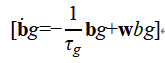
whereis the correlation time and is the driving noise. If these parameters are configured incorrectly, the filter may estimate bias too slowly or interpret vehicle motion as sensor drift.
Allan variance is widely used to separate angular random walk, bias instability, and rate random walk across different averaging intervals. However, Allan analysis should be performed at representative temperatures, sampling rates, and filter settings. A result obtained from a long stationary laboratory test does not fully describe behavior under vibration or thermal change.
Angular Random Walk and Short-Term Attitude Quality
Angular random walk characterizes the contribution of white rate noise to integrated angle uncertainty. It is especially important when high-quality external attitude or position updates are temporarily unavailable.
Noise values must therefore be translated into the actual estimator sampling interval and state model rather than copied directly from a datasheet.
Scale Factor and Dynamic Motion
Scale-factor error changes the relationship between true and measured angular rate. Unlike bias, its effect increases with motion intensity.
A simplified single-axis model is

where is the scale-factor error. During slow motion, the resulting error may be difficult to distinguish from bias. During rapid turns, the scale-factor contribution becomes much larger.
This distinction matters for vehicles, stabilized platforms, and industrial equipment that experience wide dynamic ranges. A static test may confirm low bias noise while failing to reveal scale-factor nonlinearity or saturation behavior. Engineers should use multi-rate turntable tests or application-representative rotational profiles when possible.
Axis Misalignment and Cross-Axis Sensitivity
The gyroscope sensing axes are not perfectly orthogonal, and the installed IMU frame is not perfectly aligned with the vehicle frame. These errors cause motion around one axis to appear on another.
If the installation transformation is represented by , both the sensor calibration matrix and mechanical mounting transformation must be estimated. Treating them as one ideal alignment can leave residual errors that become significant during
Bandwidth, Output Rate, and Latency
A higher output data rate does not guarantee a wider usable bandwidth. Internal filtering, communication buffering, and host-side processing all affect the effective measurement delay.
Wide bandwidth preserves rapid motion but admits more noise. Narrow filtering improves apparent noise performance but introduces phase delay. If the gyroscope measurement represents an earlier physical state than a camera, GNSS, or wheel-speed measurement carrying the same timestamp, the estimator observes false disagreement.
Timing error can be approximated as an angular-rate-dependent attitude error:
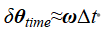
At an angular rate of 100 degrees per second, a 5 ms synchronization error corresponds to approximately 0.5 degrees of angular displacement. This can exceed the permissible attitude error of many navigation and control applications.
System specifications should therefore include timestamp resolution, timestamp origin, jitter, deterministic latency, communication delay, and clock synchronization. Research using MEMS gyroscopes for clock synchronization demonstrates that microsecond-level timing alignment can materially improve multi-sensor consistency.
Fusion Architecture and the Role of the Gyroscope
Loosely Coupled and Tightly Coupled Systems
In a loosely coupled GNSS/INS system, the inertial solution is corrected by GNSS-derived position and velocity. This architecture is relatively simple but normally requires a valid GNSS navigation solution before an update can occur.
A tightly coupled architecture processes more fundamental GNSS observations, such as pseudorange and Doppler. It may continue using partial satellite information when a complete GNSS solution is unavailable. The gyroscope still governs short-term attitude propagation, but the tighter architecture can preserve observability under more difficult signal conditions.
The same principle applies to visual-inertial and LiDAR-inertial systems. Loose coupling combines independently estimated poses. Tight coupling uses image features, point residuals, or other raw observations directly in a common estimator. Tight coupling can exploit more information but increases sensitivity to calibration, timing, and model correctness.
Centralized and Federated Filtering
A centralized extended Kalman filter incorporates all sensor measurements into one state vector. It can preserve cross-correlations and use information efficiently. Its weakness is fault propagation: an incorrect covariance, bad calibration, or undetected outlier may contaminate the common state.
A federated architecture assigns different sensor combinations to local filters. Their outputs are checked and then combined by a master filter. This structure supports fault isolation and reconfiguration when GNSS becomes unreliable, an odometer slips, or one inertial channel fails. Adaptive federated filtering can modify information-allocation factors according to local-filter consistency.
No architecture is universally superior. A centralized filter may be suitable for a compact, well-characterized sensor suite. A federated structure becomes attractive when sensors have different failure modes, update rates, or availability conditions.
IMU Arrays and Virtual Gyroscopes
Combining several gyroscopes can reduce independent noise and improve fault tolerance. Under ideal assumptions, averaging N independent sensors reduces the variance of uncorrelated noise to approximately  of that of a single sensor, corresponding to a reduction in noise standard deviation by a factor of .
Real sensor arrays rarely satisfy those assumptions. Common temperature, shared vibration, power-supply disturbances, mounting stress, and manufacturing similarity introduce correlated or systematic errors. Increasing the sensor count may then produce a more confident estimate without a proportional improvement in accuracy.
Maximum-likelihood and Kalman-based methods can model the covariance of multiple inertial sensors. However, the covariance must include cross-correlation when it is significant.
Faizullin and Ferrer proposed selecting individual gyroscope and accelerometer axes according to their estimated systematic error rather than averaging every measurement. Their experiments reported an improvement of up to 20% over an averaged virtual estimator for the tested configuration. The result illustrates an important system principle: discarding a poorly behaving measurement can be better than assigning equal trust to all available sensors.
For a detailed discussion of redundant inertial sensing, see our MEMS IMU array technology review.
Failure Modes That Nominal Specifications Do Not Reveal
A practical fusion system must distinguish normal noise, temporary degradation, and permanent failure.
Relevant gyroscope failure modes include:
- sudden bias steps;
- gradual thermal drift;
- frozen output;
- packet loss;
- timing jumps;
- saturation;
- increased noise;
- intermittent axis failure;
- vibration-induced error;
- corrupted calibration coefficients.
Innovation monitoring is commonly used for detection. If the residual is
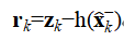
with innovation covariance
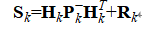
then the normalized innovation squared is
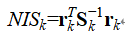
The NIS can be compared with a chi-square threshold. A persistent exceedance suggests that the measurement or its assumed uncertainty is inconsistent with the current model.
A single threshold is not sufficient. Aggressive motion, wheel slip, GNSS multipath, visual tracking loss, or vibration can also enlarge residuals. Reliable fault detection combines statistical tests with temporal persistence, sensor-to-sensor comparison, operating context, and physical limits.
Failure-resilient multi-IMU visual-inertial research shows that redundancy must be accompanied by explicit detection and isolation logic. Wavelet-based multi-scale analysis may further separate high-frequency noise from slower drift, although the decomposition level and threshold must be validated for the application.
Industry Pain Points and Limitations of Common Solutions
One industry problem is overreliance on typical datasheet values. A typical bias-instability figure does not define worst-case behavior across temperature, vibration, bandwidth, and production variation.
Another problem is covariance tuning based only on stationary data. A filter that performs well on a bench may become inconsistent during dynamic motion because its noise model excludes scale-factor error, timing uncertainty, or vibration-induced effects.
A third problem is assuming that additional sensors always increase reliability. Redundancy without independent failure modes provides limited protection. If several sensors share power, timing, thermal, and mechanical conditions, one disturbance may affect all of them.
Machine-learning compensation can model nonlinear temperature or temporal behavior, but it also introduces limitations. Performance depends on the coverage of the training data, and uncertainty outside the training distribution can be difficult to quantify. Hybrid EKF and recurrent-neural-network methods have demonstrated improved localization in experimental scenarios, but deterministic validation and safe fallback behavior remain necessary for deployment.
A Practical Gyroscope Selection and Validation Workflow
At Andelu, we recommend selecting a gyroscope from the system error budget rather than from one isolated specification.
Step 1: Define the Mission Profile
Specify maximum angular rate, required attitude accuracy, external-aiding frequency, expected outage duration, temperature range, vibration spectrum, shock level, startup time, and acceptable fault-recovery time.
Step 2: Convert Mission Requirements into Sensor Limits
Bias stability determines outage drift. Angular random walk affects short-term attitude uncertainty. Scale factor and nonlinearity affect dynamic manoeuvres. Bandwidth and latency affect control and fusion consistency. Environmental specifications determine whether calibration remains valid.
Step 3: Verify Calibration and Timing
Test bias, scale factor, non-orthogonality, temperature coefficients, warm-up behavior, timestamp jitter, and end-to-end latency. Confirm that all measurements are transformed into consistent coordinate frames and time references.
Step 4: Tune the Estimator with Representative Data
Estimate process and measurement covariance from data collected under intended bandwidth, temperature, vibration, and dynamics. Evaluate normalized innovation and estimation-error consistency rather than relying only on final RMS position error.
Step 5: Perform Outage and Fault Injection
Introduce GNSS interruptions, wheel slip, visual degradation, gyro bias steps, packet loss, frozen output, and timing offsets. Measure drift rate, filter recovery, false-alarm rate, isolation time, and continuity of output.
Step 6: Validate Before Production
Repeat testing across multiple units and environmental cycles. Datasheet comparison is a screening step, not final evidence of system suitability.
Our MEMS IMU selection guide explains how bias, random walk, range, bandwidth, temperature, and synchronization affect navigation performance. Engineers working on vehicle systems may also consult our multi-source vehicle navigation analysis.
Conclusion
In a multi-sensor fusion environment, gyroscope performance is a property of the complete system. Bias controls the rate of attitude divergence during aiding gaps. Angular random walk affects short-term propagation. Scale factor and misalignment dominate under dynamic motion. Temperature, vibration, and acceleration sensitivity determine whether laboratory calibration remains valid. Timing determines whether otherwise accurate measurements are mutually consistent.
Fusion does not remove these errors automatically. It can correct only those states made observable by the available measurements and motion. Likewise, redundant gyroscopes improve reliability only when their errors, correlations, synchronization, and failure modes are modeled.
At Andelu, we evaluate inertial products in relation to the customer’s navigation architecture, motion profile, interface, environmental exposure, and validation method. This system-level approach helps distinguish a sensor limitation from a calibration, timing, or estimator problem and supports an evidence-based selection before production integration.
References
[1] Nikolic J, Furgale P, Melzer A, et al. Maximum likelihood identification of inertial sensor noise model parameters [J]. IEEE Sensors Journal, 2016, 16 (1): 163-176.
[2] Rehder J, Nikolic J, Schneider T, et al. Extending Kalibr: Calibrating the extrinsics of multiple IMUs and of individual axes [C]. Proceedings of the IEEE International Conference on Robotics and Automation, 2016: 4304-4311.
[3] Faizullin M, Kornilova A, Akhmetyanov A, et al. Twist-n-Sync: Software clock synchronization with microsecond accuracy using MEMS gyroscopes [J]. Sensors, 2021, 21 (1): 68.
[4] Xu X, et al. An indoor mobile robot positioning algorithm based on adaptive federated Kalman filter [J]. IEEE Sensors Journal, 2021, 21 (20): 23098-23107.
[5] Skog I, Nilsson J O, Händel P, et al. Inertial sensor arrays, maximum likelihood, and Cramér-Rao bound [J]. IEEE Transactions on Signal Processing, 2016, 64 (16): 4218-4227.
[6] Faizullin M, Ferrer G. Best axes composition extended: Multiple gyroscopes and accelerometers data fusion to reduce systematic error [J]. arXiv Preprint, 2022: arXiv:2209.08895.
[7] Eckenhoff K, Geneva P, Huang G. Sensor-failure-resilient multi-IMU visual-inertial navigation [C]. Proceedings of the IEEE International Conference on Robotics and Automation, 2019: 3542-3548.
[8] Zhu H. Research on the application of multi-scale and multi-sensor fusion algorithm in MEMS gyroscope data processing [J]. Journal of Physics: Conference Series, 2021, 2023 (1): 012039.
[9] Huang Z, Ye G, Yang P, et al. Application of multi-sensor fusion localization algorithm based on recurrent neural networks [J]. Scientific Reports, 2025, 15: 8195.
[10] Bancroft J B, Lachapelle G. Data fusion algorithms for multiple inertial measurement units [J]. Sensors, 2011, 11 (7): 6771-6798.
[11] Xue L, Jiang C Y, Chang H L, et al. A novel Kalman filter for combining outputs of MEMS gyroscope array [J]. Measurement, 2012, 45 (4): 745-754.
[12] Forster C, Carlone L, Dellaert F, et al. On-manifold preintegration for real-time visual-inertial odometry [J]. IEEE Transactions on Robotics, 2017, 33 (1): 1-21.