
مقدمه
At Andelu, we recognize the accelerometer as a core sensing component of an inertial navigation system. It is used to measure the linear acceleration of a vehicle in inertial space. One integration of acceleration produces velocity, and a second integration produces position. Therefore, accelerometer accuracy directly determines the performance of inertial navigation and inertial guidance systems.
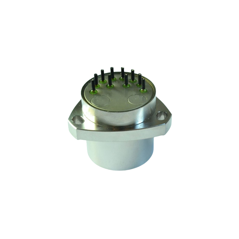
Accelerometer technology has developed over several decades, from early pendulous integrating gyroscopic accelerometers and liquid-floated pendulous accelerometers, to today’s mainstream quartz flexible accelerometers and MEMS resonant accelerometers, and finally to emerging atom accelerometers. This evolution reflects a continuing pursuit of higher accuracy, smaller size, lower cost, and greater reliability. Quartz flexible accelerometers are dry accelerometers developed from liquid-floated pendulous accelerometers. They were first successfully developed in the 1960s by the U.S. company Sundstrand Data Control. The subsequent QA-2000 and QA-3000 series became representative high-performance inertial-grade accelerometers. China began developing quartz flexible accelerometers in the early 1980s, and a number of organizations, including aerospace institutes, naval research institutes, universities, and defense laboratories, have carried out related research. This article systematically reviews quartz flexible accelerometer technology from four aspects: working principle, structural composition, application fields, and development trends.
Working Principle
Force-Balance Closed-Loop Servo Principle
A quartz flexible accelerometer uses a force-balance closed-loop servo principle to measure acceleration. When acceleration acts along the input axis of the accelerometer, the proof mass, consisting of the quartz pendulum and torque-motor coils, deviates from its equilibrium position under inertial force and produces an inertial torque:
Tᵢ = mLa
where m is the mass of the pendulum assembly, L is the distance from the center of mass of the pendulum assembly to the quartz flexure beam, and a is the input acceleration.
The deflection of the pendulum assembly changes the distance between the upper and lower plates of the differential capacitive position sensor, producing a differential capacitance change:
ΔC = Kpθ
where θ is the angular displacement of the flexure beam, and Kp is the transfer coefficient of the differential capacitive position sensor.
After the differential capacitance signal is amplified and processed by the servo circuit, it provides feedback current I to the torque-motor coil. The torque-motor coil produces an electromagnetic feedback torque in the permanent-magnet field:
Tₑ = KtI
where Kt is the torque coefficient of the torque motor. When the pendulum assembly is in force balance, Tᵢ = Tₑ, and therefore:
I = mLa/Kt
That is, the current in the torque-motor coil is proportional to the input acceleration. The magnitude and direction of acceleration can therefore be determined by detecting the current.
Differential Capacitive Detection Principle
الف quartz flexible accelerometer uses a variable-gap differential capacitive position sensor. Assume that the plate spacing before the quartz pendulum moves is d₀ and the initial capacitance is C₀. When the pendulum assembly moves upward, the upper and lower capacitances change differentially:
C₁ = εA/(d₀ − x), C₂ = εA/(d₀ + x)
The differential capacitance output is:
ΔC = C₁ − C₂
When x << d₀, the relationship can be approximated as linear:
ΔC ≈ 2εAx/d₀²
Mathematical Model
The system block diagram of a quartz flexible accelerometer can be represented as follows: the input acceleration is converted into torque by the pendulum assembly, and a closed loop is formed through the mechanical characteristics of the sensor head, the capacitive sensor, the servo amplifier, the torque motor, and other stages. Under static conditions, the pendulum assembly is at its equilibrium position, and the circuit output equation can be written as:
Uₒ = Kᵢa
where the scale factor Kᵢ is:
Kᵢ = KᵦKₜ
Normally, KₚKₐ >> 1, and therefore:
Kᵢ ≈ KᵦKₜ
where Kᵦ is the pendulousness of the pendulum assembly, and Kₜ is the scale factor of the torque motor. It can be seen from the above equation that the accelerometer scale factor is mainly determined by the pendulousness of the quartz pendulum and the scale factor of the torque motor.
Structural Composition
A quartz flexible accelerometer consists of two parts: the sensor-head assembly and the servo-circuit assembly.
Sensor-Head Assembly
The sensor-head assembly includes three parts: the proof-mass assembly, the upper torque-motor assembly, and the lower torque-motor assembly.
The proof-mass assembly consists of a coated quartz pendulum and two torque-motor coils bonded to it. The quartz pendulum is fabricated from fused quartz by chemical etching. Synthetic quartz has good stability, a low elastic modulus, a small elastic aftereffect, and a low coefficient of linear expansion, which helps improve instrument stability and repeatability. A gold film is vapor-deposited on the pendulum in a specified pattern to form the two capacitor plates of the capacitive sensor as well as the leads for the sensor and torque motor. The torque-motor coils and the central blade of the quartz pendulum form the pendulous mass. Through two flexible suspension beams, the outer ring of the pendulum is fixed between the two torque-motor assemblies by six bosses on both sides, allowing the pendulous mass to become a proof mass with an ideal single-degree-of-freedom elastic constraint.
The differential capacitive position sensor adopts a variable-gap structure. The moving capacitor plates are formed by vacuum-deposited films on the upper and lower surfaces of the quartz pendulum, while the fixed plates are formed by annular quartz plates. The resolution of this position sensor is twice that of an ordinary position sensor. It effectively improves interference resistance and significantly improves linearity.
The torque motor uses a permanent-magnet coil structure. Its magnetic circuit consists of two opposing magnetic circuits that are independent yet mutually complementary, forming a push-pull structure. This compensates for nonlinear error, reduces electromagnetic interference, and improves permanent-magnet utilization. The magnets, pole pieces, and upper and lower torque motors form a closed magnetic circuit, while the two coils on the proof mass form a push-pull permanent-magnet torque motor. The small gap between the torque-motor magnetic circuit and the pendulum assembly produces air damping during pendulum movement. At the same time, the torque motor generates back electromotive force and electromagnetic damping, creating favorable conditions for developing the flexible accelerometer.
Servo-Circuit Assembly
The servo circuit includes a differential capacitance detector, an integrator, and a transconductance/compensation amplifier. Taking the HB309 hybrid servo circuit as an example, it mainly consists of dual regulated power supplies CW78M09/CW79L09, a differential capacitive voltage converter HT15, a servo power-amplifier circuit LB314, and a correction network.
The HT15 differential capacitive voltage converter contains a triangular-wave generator, a differential capacitance detector, an integrating amplifier, and a preamplifier. It converts a small capacitance change in differential-capacitance mode into a current signal. The HT15 is packaged in an H16-02 flat black-ceramic hermetically sealed package. Its operating temperature range is −55 to +125 °C for military-grade applications, and its oscillator frequency is 400 kHz.
The LB314 servo power-amplifier circuit converts the output voltage from the current integrator into current and feeds it back to the torque-motor coil. It uses a dual-trace high-impedance circuit output mode, separating the feedback network from the torque-generating circuit. This avoids the influence of feedback-network noise on the readout circuit, increases the DC gain of the circuit, effectively reduces resistance values, and supports miniaturized circuit design.
The triangular-wave generator acts as the carrier power supply of the differential capacitance detector and modulates the signal. The output of the differential capacitance detector is an electrical signal proportional to the differential output of the capacitive sensor. The integrator and transconductance/compensation amplifier compensate and correct the signal to improve the static and dynamic characteristics of the system. The final stage supplies the torque-motor coil with a constant-current rebalancing signal. Together with the differential capacitive sensor and the proof mass, these circuits form a complete force-balance closed-loop system.
Application Fields
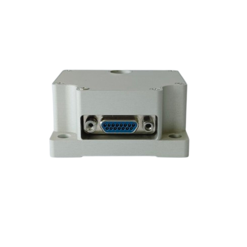
In aerospace and defense, quartz flexible accelerometers are used in platform and strapdown inertial references for missiles; aircraft navigation platforms and inertial references; inertial navigation platforms and platform leveling for long-range ships; high-performance autopilots and flight control; and inertial measurement for launch vehicles and spacecraft.
In airborne gravimetry, the quartz flexible accelerometer is a core sensor of the strapdown airborne gravimeter and is used to measure gravity anomalies.
In industrial and civil applications, quartz flexible accelerometers are used for acceleration measurement in various vehicles, including overload, braking, and motion recording; for measuring shaking, vibration, and inclination of towers, bridges, dams, and buildings; for controlling oil-well drilling direction; for seismic physical measurement and object vibration measurement; for calibration and verification of vibration, shock, and centrifuge test equipment; for recording acceleration in sports; and for environmental vibration monitoring.
In low-frequency vibration calibration, the quartz flexible accelerometer is a core technology unit of low-frequency and ultra-low-frequency vibration calibration systems. A fully digital quartz flexible accelerometer can achieve a resolution of 20 μg and stability better than 100 μg.
Development Trends
Continuous Accuracy Improvement
MEMS resonant accelerometers are rapidly progressing from tactical-grade to navigation-grade and even strategic-grade accuracy. Products from companies such as Emcore and Honeywell have achieved bias stability of 0.1 μg to 1 μg. In the next 3 to 5 years, navigation-grade MEMS accelerometers are expected to broadly replace traditional quartz flexible accelerometers and become the mainstream choice for medium- and high-accuracy inertial navigation systems.
Digitalization and Intelligence
A fully digital servo loop realizes the digitalization of the entire closed-loop control process of the accelerometer. Through system-model identification and digital-controller design, targeted compensation can be applied according to the actual parameters of each accelerometer sensor head, solving the parameter-mismatch problem between the sensor head and the servo loop. In the future, accelerometers will integrate self-calibration, self-compensation, and fault diagnosis and become part of intelligent sensing units.
New Materials and Processes
Beryllium has become a next-generation precision-instrument material because of its high stiffness, good thermal conductivity, and compatibility between its thermal expansion coefficient and those of other structural materials. Applying it to quartz flexible accelerometers can improve accuracy, reduce total instrument mass by 25%, and shorten stabilization time by 30%. MEMS processing technologies such as deep reactive ion etching can achieve submicron and smaller feature sizes, further improving the processing accuracy of flexure beams.
New- Principle Accelerometers
Atom accelerometers are based on cold-atom interferometry and can theoretically achieve accuracy on the order of 10⁻¹⁰ g. Exail’s three-axis quantum sensor has achieved an accuracy of 6 × 10⁻⁸ g. Micro-optical accelerometers use optical interference to detect acceleration and have potential advantages including high sensitivity and resistance to electromagnetic interference. With the progress of integrated photonics and micro/nano quantum technology, miniaturized atom accelerometers are expected to emerge.
Conclusion
As a mainstream product among mechanical pendulous accelerometers, the quartz flexible accelerometer has been widely used in land, sea, air, and space applications because of its high resolution, high stability, moderate size, and high reliability. After decades of development, its design theory, manufacturing processes, and servo circuits have all become mature, giving the technology a high level of readiness.
Through advances in key technologies such as small-range high-accuracy design, fully digital servo loops, system-model identification, and digital-controller design, quartz flexible accelerometer performance continues to improve and its application fields continue to expand. In the future, with further development of new materials, new processes, digitalization, and intelligent technologies, quartz flexible accelerometers will continue to evolve toward higher accuracy, smaller size, lower cost, and higher reliability, providing essential technical support for inertial navigation and precision measurement.